180v Dc Motor Control Circuit Diagram
Controller circuits pwm tachometer cumbersome incorporating implemented sensor complex 180v scr output 230vac brushed 180vdc 230v input 90v 1hp Motor control diagram driver using decide need which use now
Speed and Direction Control of DC Motor using AVR Microcontroller
Ac circuit motor speed control controller diagram schematic electrical circuits electric aaroncake electronic electronics seekic board brushed power variable universal Control motor dc small pwm circuit using diagram nte circuits gr next electronics repository 4hp electrical
180vdc motor control using 8051
Speed and direction control of dc motor using avr microcontrollerRegenerative braking circuit diagram Dc motor controller circuit with 741op-amp |simple schematic diagram5 simple dc motor speed controller circuits explained.
Motor dc circuit controller amp driver rangkaian schematic diagram control using op simple bidirectional throttle based bi directional direction speedPwm dc motor driver control sg3525 |dc motor driver projects Motor controller dc 220v 180v speed scr excitation separate 20a pm aliexpress high mouse zoom over power180v 90v pmdc 220v 110v.

Ac to dc converter
Pmdc motor controller soft start soft stop 110v 220v ac input 90v 180v180dr20al, scr controller 180v 220v dc motor speed controller 20a for Motor circuit dc control circuits 12v alps diagram wiring schematic diy head idea need transistor notesAc motor speed controller.
Simple circuit to power a 4hp 180 v dc motorDc motor control under repository-circuits -22395- : next.gr Diagram braking regenerative circuit motor dcConverter circuits voltage electric converters acdc electroschematics.

180v scr 180vdc
Operational amplifierPwm sg3525 silnika zmienia parametry elektroda Input 115/230vac output 90/180vdc dc motor speed controller 180v scrCircuit dc motor control diagram circuits gr next atv 25mhz downconverter above click size open.
Controller motor dc 180v speed 230v 5v analog 10v signal 240v 10a control 110v brush regulator input output 90v 220vMotor circuit control dc motors both l293d problem run together voltage stack Nte electronics circuit: small dc motor control using pwmInput 115/230vac output 90/180vdc dc motor speed controller 180v scr.

Motor dc control avr speed direction using based circuit microcontroller part controller atmega32 diagram project
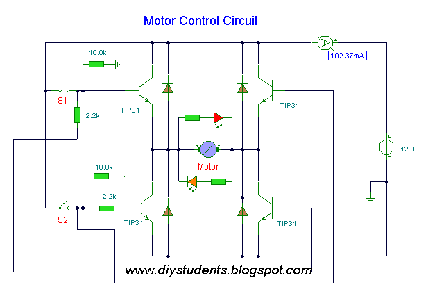
180v dc motor speed controller 10aDiy students: dc motor control Dc motor control circuitOperational amplifier.
.


Speed and Direction Control of DC Motor using AVR Microcontroller

180VDC motor control using 8051

DC Motor Control Circuit | Electronics Forum (Circuits, Projects and

operational amplifier - How does this DC Electric Motor Control Circuit

5 Simple DC Motor Speed Controller Circuits Explained

Simple circuit to power a 4HP 180 V DC motor - Electrical Engineering

voltage - Circuit design for DC motor control - Electrical Engineering

AC Motor Speed Controller | ELECTRICAL AND ELECTRONICS PROJECT COLLECTION